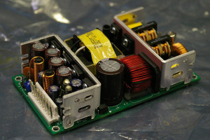
Image of the failed power supply in question…
We recently received a switching power supply that failed in the field so we took the opportunity to do some troubleshooting and discuss the process here on CircuitBoardProblems.com!
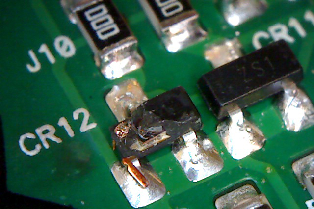
Of course, like any good troubleshooters (and according to the PCB Troubleshooting Flowchart) we gave the power supply a good visual inspection. On the bottom side of the PCB, this turned up.
Obviously, this poor little diode has been overstressed but is this the only problem on the board?

Image of surface mounted diode that was subjected to significant over voltage.
Further visual inspection yielded no additional issues so now it was time to do some power-off testing. The easiest approach was to create a quick analog signature analysis test using our trusty Huntron Tracker.
Since we do not have schematics for this power supply, creating a test for it means that we address the signature capture directly on the component pins. When considering which components to probe we generally end up testing most or all of the semiconductors and connectors on the circuit board. The reasoning behind this approach is that these components connect to the majority of the “nets” on the PCB therefore reducing the number of points versus probing EVERY component. So, with this method in mind, we created a Tracker test that included all of the diodes, transistors and ICs. We also included the connectors to test for possible issues caused by a surge or spike coming onto the board from the outside world (see PCB Troubleshooting – Start with the Connectors!).
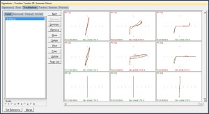
Using a good power supply, we ran the Tracker test to capture and store signatures to use for comparison. Once that was complete, we ran the same test on the bad power supply and viewed the results. Of course we expected the damaged diode CR12 to fail but several other components showed important signature differences. Initially the most important failures were those on U1, a ML4800IS Power Factor Correction and PWM Controller from Fairchild. All but seven of the pins showed resistance or voltage breakdown differences which indicates that U1 is definitely damaged. The most significant signatures are shown below.
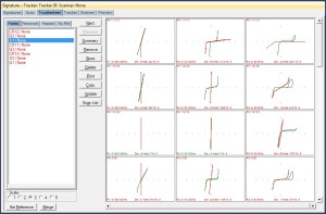
At this point in the troubleshooting process, we decided to replace U1 and CR12 and then rescan the bad power supply. We anticipated that we would see additional problems but rescanning allows us to eliminate U1 and CR12 and focus on connected components. The wrong thing to do at this point would be to power ON test the unit as we could cause more problems (such as blowing up the components we just replaced!). Here are the results of the rescan.

Results of second test pass on bad power supply with signature failures on U4 – click to view full size
As you can see and to our surprise, only one component (U4, pins 1 and 3) failed and the failed analog signatures do not indicate any significant issues. This means that CR12 and U1 were the cause of most of the signature failures on the PCB.
What is the next step? What caused the failure to occur? Stay tuned for “Troubleshooting a Switching Power Supply – Part 2”!
Thank you.

Outstanding,
Thank you for this reports.
Alfredo